
Getting the Beam Look
A practical guide to the 3D beam modes and their sliders — how to get a specific look, fix a preview that reads wrong, and inspect the bundled test patterns before hardware calibration.
The 3D Beam Viewer page lists every control. This one is the working guide: what to reach for when you want a particular look, and what to change when the preview does not read the way you expect.
It is worth knowing up front that the beam modes are a ladder, not a menu of styles. Each step is a closer approximation of a real laser than the one before it, and they trade cost for realism in that order. Picking the "best" one is not always right — the plainest modes are often the most useful, for reasons below.
Every beam mode is fully interactive on the free tier. Nothing is locked behind a paywall for evaluation — paid modes simply render with a BeamTracer watermark until you upgrade. You can try all seven against your own files before deciding whether any of them are worth paying for.
The Ladder at a Glance
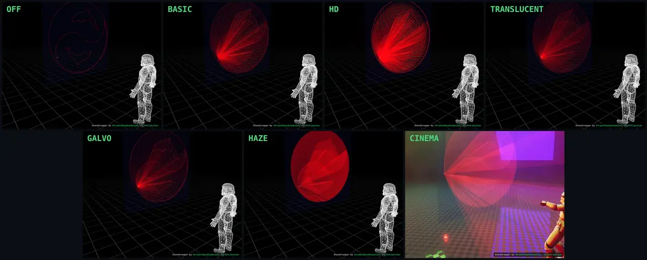
| Mode | Tier | Reach for it when |
|---|---|---|
| Off | Free | You are checking content structure, or you want the fastest possible playback |
| Basic | Free | You want to see beam paths clearly with minimum overhead |
| HD | Pro | You want beams with real thickness and depth while keeping paths readable |
| Translucent | Bundle | Beams are hiding the pattern behind them and you need to see through |
| Galvo | Bundle | You want a point-by-point simulation of the scan sequence |
| Haze | Bundle | You are judging how the beams will look in a hazed room |
| Cinema | Studio | You are producing a client preview, a pitch image, or promo material |
The useful rule: for inspecting stored geometry and planned coverage, work in the plainer modes. For presentation, move up the ladder. Every mode is a visualization; none measures the physical projector, atmosphere, venue, or exposure.
The Two Controls That Decide the Look
Almost every "how do I get that look" question comes down to two controls in the Scene panel.
Beam Mode — the biggest single change. Move up the ladder for realism, down for clarity and speed.
Screen Height (Scr.Ht) — where the whole scan field sits in the room, adjustable from 1m to 6m. At its 1.5m default the content sits low, which is realistic for a floor-mounted projector but crowds the bottom of the frame from angled cameras. Around 2–2.5m lifts the pattern clear.
Beyond those, WIDTH (HD and Translucent) sets beam thickness, and HAZE density drives the light cone in Haze mode.
There is no glow control. A laser is never out of focus, so every mode draws the beam path sharp and exact. Nothing in the preview inflates how wide a beam appears, which is what makes the plainer modes trustworthy for inspecting simulated coverage. See Laser Clearance Reference for the limits of software planning.
Beam Color Comes From Your File
Beams are drawn in the color stored by the content. There is no separate beam color control; the viewer uses the file color in its simulation.
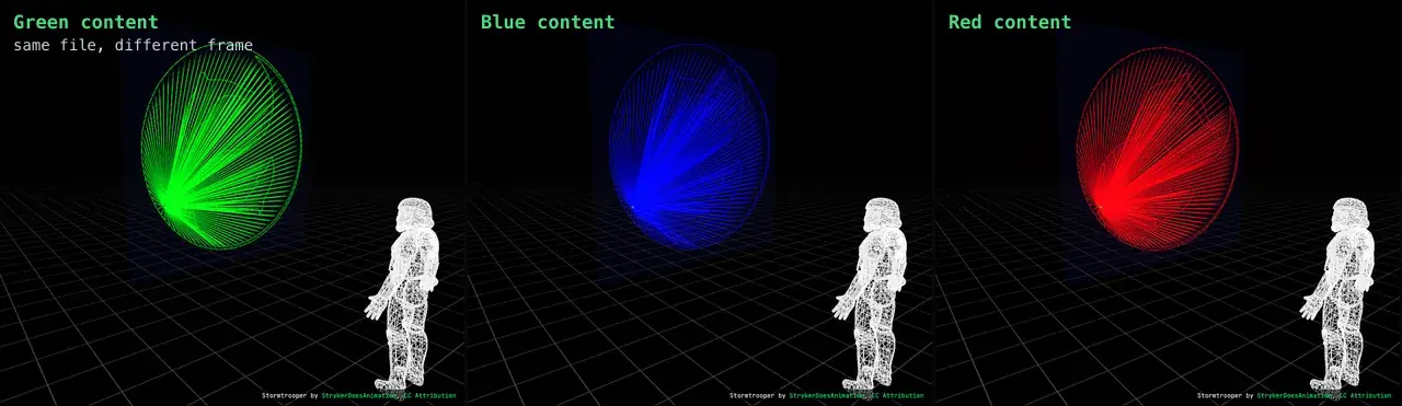
All three tiles are the same file in the same mode, at three different frames. If your beams are not the color you expect, the color is in the file, not the viewer. Load it in the 2D view and step through frames to confirm what is actually stored.
White beams are not necessarily a bug. Plenty of ILDA files contain genuinely white sections, and some animations change color partway through. Before concluding the preview is wrong, step to a frame you know is colored.
Why Complex Artwork Looks Solid
This is the most common "the 3D view looks wrong" report, and it is usually the content rather than the viewer.
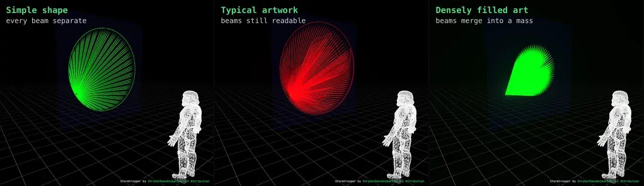
Every visible point in an ILDA frame contributes to the simulated path. A simple ring produces paths you can count. Densely filled artwork puts many paths close together, so the preview can merge them into a solid shape. Physical output can also appear dense, but its appearance depends on the projector, atmosphere, distance, and camera or observer.
If you need to see through it:
- Switch to Translucent, which is built for exactly this.
- Reduce WIDTH so each beam occupies less space.
- Move to Iso View or Side View; a head-on camera stacks every beam on top of every other one.
- Consider whether the content itself is too dense — see the Optimization Guide.
Look Recipes
Troubleshooting
The beams are a solid mass and I cannot see individual paths
Cause: Dense content. The preview merges nearby paths; physical output can also appear dense depending on the projector, atmosphere, and viewing conditions.
Fix: Translucent mode, narrower Width, an angled camera. See Why Complex Artwork Looks Solid.
Everything is washed out and too bright
Cause: In Cinema, Fog and Smoke set high for the camera you are on; in HD, Width wide enough that neighboring beams overlap.
Fix: Bring Fog and Smoke down until the beam path is crisp again, or narrow Width in HD. The beams themselves never blur.
The beams are white when my content is colored
Cause: Almost always the frame you are parked on. Many files contain white sections.
Fix: Step through frames in the 2D view to confirm what the file stores at that point.
The pattern sits low in the frame or is half behind the floor
Cause: Screen Height at its default, seen from an angled camera.
Fix: Raise SCR.HT from its 1.5m default to around 2–2.5m.
I turned on the waveform or an analysis overlay and cannot see it
Cause: The overlays draw onto the screen surface. When the screen sits low, the trace can end up level with or below the venue floor.
Fix: Raise SCR.HT, or orbit below floor level. The overlays also need SCREEN ON in Cinema mode — there is nothing to draw them onto otherwise.
Cinema mode is slow or stutters
Cause: Volumetric rendering is the most demanding mode in the product.
Fix: In Cinema's advanced section, lower RES and STEPS first — they cost the most. Leave DENOISE on; it buys back quality at lower step counts. For scrubbing and editing, drop to Basic and switch back to Cinema for the final look.
The 3D view will not start at all
Cause: Hardware acceleration unavailable or a driver problem.
Fix: See Troubleshooting. The 2D viewer stays available regardless.
Understanding Test Patterns Before Hardware Calibration
The viewer ships a TEST SUITE in the left panel. These reference files help you inspect stored geometry and understand what qualified technicians evaluate on hardware. BeamTracer does not tune, measure, or certify a projector.
| Button | Pattern | Tells you |
|---|---|---|
| PATTERN | The ILDA test pattern | Scanner speed, damping, symmetry, size and centering |
| ORIENT | Orientation test | Whether your X/Y axes are mapped and polarised correctly |
| BLANKING | Blanking test | Whether the laser switches on and off at the right moment |
| GRID | Grid test | Whether point distribution is even across the field |
BeamTracer previews and exports these files. Hardware adjustment requires the projector or scanner manufacturer's instructions and the official test-pattern procedure.
What "30K" Actually Means
This is the single most useful thing the test pattern teaches, and it is widely misunderstood.
A projector advertised at a given kpps is stating a coordinate-update rate. The useful scanner test condition includes the pattern, point rate, and optical scan angle together. Results at one condition do not predict every frame or angle.
ILDA describes the 12K pattern at about 15° optical and the 30K pattern at about 8° optical as standard reference conditions. A wider angle asks the mirrors to travel farther in the same time, so rate claims are only meaningful with their pattern and angle attached. See the official ILDA test-pattern procedure.
Treat a plain kpps number as incomplete until you know the associated test pattern and angle.
Reading the Pattern
The relationships below help you read a test result. Scanner tuning can damage hardware if performed incorrectly; ILDA says it should be done by a knowledgeable person. Follow the official sequence and the manufacturer's instructions rather than adjusting a projector from this summary alone.
Check the inverts. The Y text should read at the top and the X text at the right. If either is flipped, correct the axis polarity before tuning anything else — every later step depends on it. The ORIENT test isolates this same question.
Inspect the inner square corners. Overshoot, ringing, and rounded corners are response symptoms. Use the official procedure to distinguish gain, damping, rate, and angle effects before making a hardware adjustment.
Compare the circle with the square. At the specified test condition, the circle should meet the midpoint of each edge. A mismatch is diagnostic evidence, not proof of one particular adjustment.
Check whether the circle is round. An ellipse shows that the X and Y responses differ at the test condition. Use the official procedure and manufacturer guidance to isolate the cause.
Check the test angle. Record the optical scan angle used for the test together with the point rate. A result without the angle does not describe the complete test condition.
Check centering. The crosshair should sit in the middle of the test field. Record any offset and follow the manufacturer's alignment procedure.
The pattern also carries a blanking section — horizontal lines crossing a small vertical mark, and a row of dots along the bottom. A qualified technician uses those features to evaluate color timing and blanking behavior under the official procedure. In BeamTracer, they remain stored reference geometry.
Choosing a Hardware Test Condition
Do not search for a scanner limit by increasing rate until the image fails. ILDA warns that scanners can be damaged by careless adjustment and that oscillation should never be allowed. Use the rate and angle specified by the manufacturer, then follow the official test procedure with qualified personnel.
The viewer exposes playback speed as FPS. Required points per second is the total records in the frame, including blanked records, multiplied by FPS, so stepping FPS up (>) raises the calculated demand. This is file arithmetic and preview cadence; it is not a physical scanner test. A Device Profile stores the comparison rate you choose for BeamTracer's analysis.
BeamTracer's load percentage, heat map, and 3D preview cannot establish a safe scanner setting or optical exposure. Keep projector interlocks, physical limits, masks, and the manufacturer's operating procedures in effect.
What the Test Pattern Cannot Tell You
The pattern characterizes scanner response at one operating point — one rate and one angle. It is not a full description of the projector. Testing another condition requires the manufacturer's limits and the official procedure.
It also cannot separate every content issue from every hardware response. Dense frames and long coordinate jumps can contribute to rounded corners or flicker. Review that side with the Optimization Guide and the Stress Heat Map.
Further Reading
3D Beam Viewer
The full control reference for every mode and panel
The ILDA Test Pattern
What each element of the pattern is for
Optimization Guide
Preparing point budgets and coordinate paths
Laser Clearance Reference
Planning overlays and operator responsibilities
Device Profiles
Comparing content with a chosen point rate
Understanding PPS
Scanner ratings and point-rate calculations