
Hardware Control
MIDI, OSC, and laser DAC setup for OSC-1 — Web MIDI, MIDI Learn, Helios WebUSB, Ether Dream, and LaserCube.
OSC-1 supports MIDI control, bidirectional OSC, and direct laser DAC output. Use Chrome or Edge: laser DAC output needs WebUSB, which no other browser implements. MIDI also works in Firefox after a one-time permission prompt, and is unavailable in Safari — see Browser Compatibility.
MIDI
OSC-1 uses Web MIDI — no drivers needed. Connect your MIDI device before opening the browser.
Enabling MIDI
- Open OSC-1 with the MIDI device connected
- Open Settings → MIDI and accept the MIDI permission prompt; Firefox also offers a one-time permission add-on
- Your controller appears under Connected Devices
How do I map a knob to an OSC-1 control?
Every mappable control has a small M button beside it. The same button learns a MIDI control or an OSC message (see OSC Learn). There are two ways to use it.
One control at a time
- Left-click the M button beside the control — it shows
...while it listens - Move a knob or fader, or press a pad or key, on your controller
- The mapping is saved and the button shows the CC number (a pad or key shows N and its note number, such as N36)
- Right-click the button to remove the mapping
Several controls in a row
- Open Settings → MIDI and click START MIDI LEARN. Settings closes, a MIDI LEARN bar appears at the top of the window, and every M button is outlined — even when Show MIDI Learn Buttons is off
- Click the M button of the control you want, then move a knob or press a pad. The bar names the pair, for example Mapped CC 21 ch 1 → XY Hue
- Click the next control's M button and repeat
- Click DONE or press Esc to finish
If you learn a knob that is already mapped, the new control takes it over and the bar says which mapping it replaced. Each control has one knob, and each knob drives one control.
How mapped controls behave
- Knobs and faders sweep the control across its full range.
- Pads and keys set the control while held (harder hits set it higher) and return it to its minimum on release. Pads mapped to an on/off or trigger control, such as the Shape Morph M trigger or a Morph Sequencer slot, fire once per press.
- No jumps. After you move the on-screen control or load a preset, the knob waits until it reaches the control's value, then takes over. Right after you learn a knob, it takes over straight away.
- A mapped pad or key does only its mapped job. The sampler, the step sequencer and the on-screen keyboard ignore it; unmapped pads and keys work as before.
MIDI Settings Panel
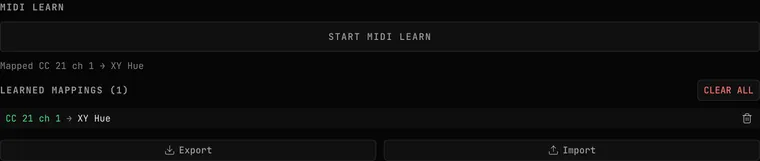
The MIDI panel in Settings contains:
- Connected Devices — every MIDI input the browser can see, updated when you plug one in or unplug it
- MIDI LEARN — START MIDI LEARN and the result of the last capture
- LEARNED MAPPINGS — each mapping as its source and control (for example CC 21 ch 1 → XY Hue). The trash button on a row removes that mapping; CLEAR ALL asks Remove all N mappings? in place, with REMOVE ALL and CANCEL. A mapping whose control is not on screen right now is marked INACTIVE and works again when the control is back
- Export / Import — save all your MIDI and OSC mappings to a JSON file and load them back later
- Program Change — which MIDI channel can switch scope presets (see below)
- An APC Mini MK2 section with a Test LEDs button and a live "LED Feedback Active" list
On a paid plan, mappings are saved in your browser and restored on your next visit; if you have already allowed MIDI for the site, mapped knobs respond as soon as the page loads. On the Free plan, mappings last until you reload.
There are no built-in controller templates — mappings are whatever you create with MIDI Learn (and export/import as JSON). For the APC Mini MK2 deep-dive, see Performance Mode.
Program Change
Send a MIDI Program Change from your controller or DAW to switch scope presets. Program 0 selects the first button in Scope Presets (Vector Display), program 1 the second, and so on through the eight built-in presets and then My Presets in the order listed. A program number past the last preset selects the last one.
Choose which channel is listened to under Settings → MIDI → Program Change:
- All channels — the default
- Channel 1 to Channel 16 — only that channel switches presets
- Off — Program Change is ignored
OSC-1 connects to MIDI when you open Settings → MIDI or start MIDI Learn, so open the MIDI settings once after loading the page. Program Change does not create a mapping and does not interrupt MIDI Learn.
See also: MIDI Setup (Shared)
Using a Real Oscilloscope
You do not need one — but if you want to drive an analog CRT from OSC-1 or from an exported file, here is what matters.
Choosing a scope
The only hard requirement is two inputs and an XY mode. Many analog scopes have it; some do not. If a listing does not say, check the manual for wording like "channel 1 provides horizontal deflection, channel 2 vertical deflection" — that is XY mode by another name. Search secondhand listings for "analog oscilloscope"; the digital storage scopes that replaced them are usually worse at this, because they sample and redraw rather than deflecting a beam continuously.
Connecting
Scope inputs are usually BNC. From an audio interface's outputs you will want ¼-inch TS to RCA cables plus BNC-to-RCA adapters, or the equivalent single cable. A few audio-monitor scopes use XLR instead of BNC.
Use an aggregate or multi-output device so you can monitor on headphones and drive the scope at the same time.
Setup order — intensity down first
Follow this order. A stationary bright dot can burn the phosphor permanently, and at the start of setup a stationary dot is exactly what you have.
- Turn intensity all the way down before anything else.
- DC-couple both inputs. AC coupling filters out the constant part of the signal, which is what positions the image — on AC the picture drifts back to center. This is the single most common first-time failure.
- Switch to XY mode.
- Raise intensity slowly until the dot just appears. No brighter.
- Center it with the horizontal and vertical position controls.
- Raise the level from your interface, not from the scope — amplifying at the scope amplifies its noise too.
- Draw a square and set VOLTS/DIV on both channels so it fills the screen and is actually square.
- Fine-tune focus last.
If the whole image sits at an angle, older units have a trace rotation trim — usually a screwdriver adjustment on the front panel.
If your graticule is rotated
Some scopes have a graticule rotated 45 degrees, so the grid reads as an X rather than a plus. Artwork intended to line up with the grid needs to be pre-rotated by −45 degrees to compensate.
A note on expectations
An old CRT has real limits. There is a well-known case of someone trying to resolve a detailed commercial oscilloscope-music release on a 1980s scope, working through several high-resolution players and two different outboard converters, getting identical wrong results every time, and eventually concluding the tube itself could not resolve the intended image.
That is worth knowing before you spend money chasing fidelity in the wrong place: a software scope is not a consolation prize for people without hardware. It is frequently more accurate than the hardware, because it is not fighting beam width, phosphor bloom, or thirty-year-old analog deflection circuitry. Use a CRT because you like how a CRT looks — that is a good reason — not because you assume it is more faithful.
Monitoring volume. XY audio is loud, shrill and dense with high frequencies, and you will be listening to it for a long time while you work. Start at minimum volume, monitor lower than feels natural, and take breaks. This is the most common real injury risk in the entire form.
OSC (Open Sound Control)
OSC is a networking protocol for real-time parameter control. OSC-1 receives it through an OSC bridge on your computer — the same bridge, on the same port, that the laser tools and Audio Visualizers use. See Which bridge to use.
Setting Up OSC
- Start your OSC bridge on the computer that runs BeamTracer.
- Open Settings → OSC.
- Under OSC Bridge, enter the bridge's BRIDGE PORT (the default is
8765) and click CONNECT. - Confirm the line under CONNECT reads Listening on ws://localhost:8765. While it reads Not connected or No OSC bridge answering … retrying, no OSC reaches OSC-1. If the bridge stops, OSC-1 reconnects on its own when it returns.
OSC Learn
OSC is learned with the same M button as MIDI; there is no separate OSC button. With the bridge connected:
- Left-click the M button beside a control. It shows
...while it listens. - Move the fader or press the button in your OSC software (TouchOSC, TouchDesigner, QLab or any show-control app).
- The button reads OSC. Hover it to see the address, for example OSC /1/fader1[0] → Scale. The number in brackets is which value of the message the control follows (0 is the first).
START MIDI LEARN works the same way for several controls in a row, from Settings → MIDI or Settings → OSC.
Only a value that moves is learned. If your software sends several addresses all the time, OSC-1 maps the one whose value changes, so keep the others still while you learn. A message with no value, such as a cue's "go", maps to a button or switch.
Range. The first value sets the range the control spans: 0 to 1 (TouchDesigner and most tracking data), −1 to 1, 0 to 127 (MIDI-style faders), or wider. If your software later sends a value past it, the range grows to fit. LEARNED MAPPINGS shows it on the row, as AUTO 0–1. Click it to type a range, then SET. AUTO lets it grow again. A switch turns on in the top half of the range, and a button fires once each time the value rises into the top half.
3D camera. The 3D controls have M buttons too: ROTATION X, ROTATION Y, ROTATION Z, ZOOM and the auto-rotate SPEED under 3D IMPORT → View Controls, and every slider in 3D CAMERA. Point a TouchDesigner or tracking stream at them to turn a model by hand or by motion. They glide to each new value instead of jumping. CAMERA SMOOTHING, under LEARNED MAPPINGS, sets how much: OFF jumps.
MIDI and OSC mappings share one LEARNED MAPPINGS list, shown in Settings → MIDI and Settings → OSC, with the same remove buttons, CLEAR ALL, Export and Import. Each control has one mapping: learning an OSC address for a control that already follows a knob replaces the knob, and the MIDI LEARN line names what it replaced. Right-click the M button to remove a mapping.
Laser blackout over OSC
Sending /beamtracer/laser/blackout to the bridge blacks out OSC-1's laser output, and /beamtracer/laser/stop stops it, exactly like the BLACKOUT and STOP buttons. These two addresses need no learning and cannot be mapped to any other control; no OSC message can arm, start or power the laser. Settings → OSC → Laser Blackout lists them. See OSC blackout.
Laser DAC Output
Stream the XY audio directly to a laser projector in real time. For all three ways to get OSC-1 onto a laser — live output, an ILDA file, or an ILDA animation from a recording — start with Show OSC-1 on a laser projector. OSC-1 uses the same Laser Output panel as every other BeamTracer laser app, so device selection, arming, power, point rate and color delay all work identically — and a projector you calibrate here is calibrated everywhere.
What follows is what is specific to OSC-1.
Orientation follows the screen
The laser draws the figure the way the scope shows it. SWAP, INV X and INV Y in the Beam Transformer turn and mirror the projection along with the screen, and the output preview shows the same orientation. If the projection is mirrored or sideways with all three off, check your projector's own axis settings with the ILDA Viewer's ORIENT test first, so the controls start from a correct baseline.
Streaming Stats
While the laser is running, the panel shows live Chunks sent, Points/chunk, and Actual PPS. A fixed status row reads WITHIN SET RATE when the stream fits your configured ceiling. When it does not, the row shows how many times over the rate it is; open Details to see which controls can bring it down. The longer explanation stays collapsed during playback so changing frame complexity does not resize the panel.
The Actual PPS dot still grades the physical workload: it turns yellow at 30k pps (good galvos required) and red at 60k pps (premium galvos required). The same 30k/40k/60k thresholds are marked on the Point Rate slider.
Inspecting the galvo preview
The output preview follows incoming Continuous XY samples in order. PREVIEW SPEED slows the on-screen scan without changing hardware output. In slow motion, the preview shows a rolling sample of the live input. If it falls behind, a notice reports skipped preview samples and the preview leaves gaps instead of joining unrelated parts of the trace. TRAIL controls how long earlier light remains visible.
When the signal stops
A laser that holds still puts all of its power on one spot, so OSC-1 turns the laser off instead of leaving a dot on the wall. How quickly depends on how the signal stopped:
- You pause or stop the source — the transport, a generator, or a track that reaches its end. The laser goes dark right away, and the notice below appears within about half a second.
- The signal keeps running but stops moving — silence inside a playing track, or an input that sits at a steady offset. The dot starts to fade after about 1.5 seconds and is fully dark by about 2 seconds; the notice appears as the fade begins.
Either way, the laser relights on its own as soon as the signal moves again; you do not need to press START again.
While the laser is held dark, Beam blanked: signal idle appears in amber under ARM in the panel, or in the safety dock at the bottom of the app when a projector is attached. The output preview goes dark with it.
A very quiet signal counts as idle too: if the whole trace stays within about 1% of the scan width, the laser treats it as a dot and blanks it. The screen is not affected — the scope keeps showing its idle dot or flat trace, because that is what the signal is doing.
This is a software safeguard, not a substitute for your projector's physical interlock, scan-fail protection and emergency stop.
Blackout from the keyboard
While a laser DAC or the DAC Simulator is connected, Esc is BLACKOUT —
even while you type in a field or a settings panel is open, and in fullscreen
(press and hold Esc, or ⌘F, to leave fullscreen). Ctrl+B (⌘B on Mac)
does the same. Ctrl+A (⌘A) presses ARM and Ctrl+S (⌘S) presses
START, but only while START is available; otherwise ⌘S still saves
your project. See
keyboard control.
Blackout from a MIDI pad
Click START MIDI LEARN in Settings → MIDI. The MIDI LEARN bar lists LASER BLACKOUT and LASER STOP: click one, then press a pad. The pad then does only that job — the synth keyboard, sampler and APC pad actions ignore it. A blackout from the pad holds until you click RELEASE BLACKOUT, and START is still needed after. MIDI cannot arm, start or change the laser's power. See MIDI blackout.
OSC-1-only output settings
These sit alongside the shared controls described in Laser DAC Output, and exist because OSC-1 streams a continuous audio waveform rather than drawn frames. Open ▶ ADVANCED under OUTPUT to reach them:
- Sync to Canvas — laser color follows the on-screen beam color (default on)
- Laser Color — manual color picker, shown when Sync to Canvas is off
- Auto-Blanking — automatically blanks the beam on large jumps
- Jump Threshold — how large a jump triggers blanking, 1–50% (shown when Auto-Blanking is on)
- Blanking Points — extra blanked points inserted at jumps, 0–20
- Dwell Points — points held at corners so the scanner settles, 0–10
- Lit Dwell — lit points held at the start of a segment, 0–5
- Point Skip — drops insignificant points to reduce scan load
Start at 25,000 pps and increase until you see overshoot artifacts, then back down 20%. This gives you your safe operating rate for the current content.